For the video of this topic click here.
If you’re converting a vehicle to electric, and want to register it, you’ll need to comply with your local regulations. In Australia that means NCOP 14.
One requirement of NCOP 14 is that your traction battery must be isolated from the chassis. There must be less than 20 mA current leakage between the HAZV traction battery and the chassis.
The guideline does not tell you how to check the leakage current, or how often, other than mentioning that a circuit or device may be used. In this article I’ll explain one manual method of checking your leakage current using just a resistor and a multimeter, and demonstrate the process on my converted Subaru Brumby.
Background
NCOP 14 states that the leakage to chassis must be less than 20 mA, measured when the vehicle is at rest. It suggests that a device or circuit may be used to check this on a regular basis, but does not require this.
Checking for such a low leakage current is beyond your average multimeter. An electrician would typically use a megohmmeter, and would typically call it by the brand name Megger. A Megger is used to test insulation resistance, and does this by applying a high voltage – much higher than a multimeter.
A neat trick is described in the United Nations standard E/ECE/324, regulation N. 100. Annex 4A on page 32 describes an ‘Isolation Resistance Measurement Method’ which uses the traction pack to provide the high voltage required to test the leakage current. Following this means that you can perform an insulation test using a voltmeter, a resistor and a calculator. No Megger required!
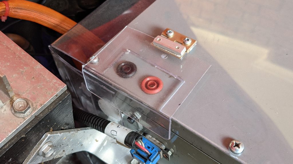
To perform the test you’ll need access to the positive and negative terminals of your traction pack. In the Brumby I’ve installed two banana sockets for this test. This allows me to connect to the traction pack with minimal risk. You don’t want to electrocute yourself while performing a safety check!
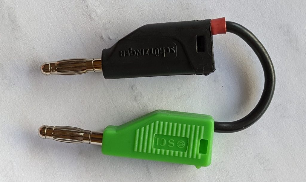
You’ll need a test resistor. Mine is 82kOhms. From the picture you can see that I’ve insulated it and attached it to banana plugs to make it easy to handle safely. The resistor itself is under the red heatshrink, inside the housing of the black plug.
Ideally this test should be easy to perform, so that you’ll do it regularly. I made myself an instruction book and a work book to record the results.
Test Instructions 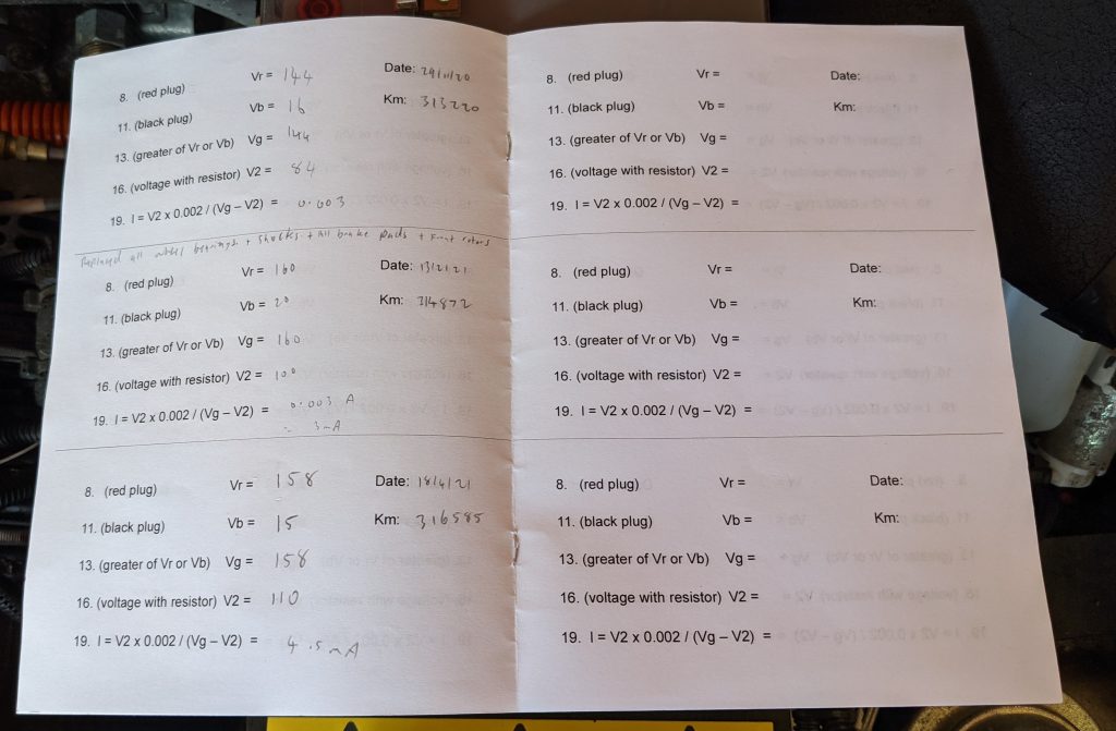
Workbook
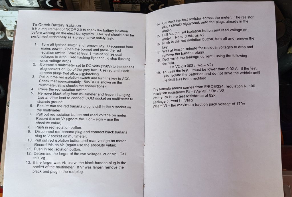
The Instructions
It may be helpful to view my video, where I follow these instructions using the Brumby.
- Isolate the traction battery so that connections can be safely made. I have a big red button for this.
- Connect a multimeter set to DC volts to the banana plug sockets. Use red and black banana plugs that allow piggybacking.
- Connect the traction battery (pull out the red button). Check that approximately 150VDC is shown on the multimeter (this checks the connections).
- Isolate the battery (press the red button).
- Remove the black plug from the multimeter and put it to one side. Use another lead to connect the vacated socket on the multimeter to chassis ground.
- Ensure that the red banana plug is still in the other socket on the multimeter.
- Pull out the red isolation button to connect the battery. Read the voltage on the meter. It may take some time to settle. Record this as Vr (ignore the + or – sign – use the absolute value).
- Isolate the battery (press the red button).
- Remove the red banana plug from the multimeter socket. Take the black banana plug and connect it to the socket instead.
- Connect the battery and read the voltage on the meter. Record this as Vb (again use the absolute value).
- Isolate the battery.
- Determine the larger of the two voltages Vr or Vb. Call this Vg.
- If the larger was Vb, leave the black banana plug in the socket of the multimeter. If Vr was larger, remove the black and plug in the red plug.
- Connect the test resistor across the meter. The resistor plugs should piggyback onto the plugs already in the meter.
- Connect the battery and read the voltage on the meter. Record this as V2.
- Isolate the battery for the last time.
- Wait at least 1 minute for residual voltages to drop and remove the banana plugs.
- Determine the leakage current I using the following formula:
- I = V2 x 0.002 / (Vg – V2)
- To pass the test, the leakage current I must be lower than 0.02 A (20 mA). If the test fails, isolate the battery and do not drive the vehicle until the fault has been rectified.
The formula in step 19 includes a number in bold (0.002) which may be different for your vehicle. To work it out you need to know two things:
- The voltage of your traction pack, Vt. For the Brumby this is 170 V (I used the fully-charged voltage).
- The resistance of your test resistor, R0. Mine is 82,000 Ohms. You may want to try a higher resistance if your traction battery voltage is higher.
The formula to calculate the number is Vt/R0. In my case 170/82,000 = 0.00207. I’ve rounded this to 0.002 for my calculations.
As you can see, this test is reasonably straightforward if your vehicle provides access to the traction pack. It is a good idea to perform the test on a routine basis, and especially if you change something with the HAZV system, such as install a new charger or controller. Don’t get complacent though, as this test involves getting up close to high voltages. One day I might develop an automated way to perform the test with a microcontroller and a couple of relays.