Build your own Battery Management System!
A Battery Management System is essential to any lithium battery, but good ones are expensive and cheap ones might not do what you need them to do. If you’re making yourself a battery, you might consider making yourself a BMS.
The Low Cost BMS is an open-source design for a battery management system. You can build this BMS yourself to monitor cells within your homemade battery. It will take you some time to do, and you may have to learn a bit along the way, but it will be cheap!
The design is based around PIC microcontrollers, and since it is open-source you can modify the design to fit your needs. For instance you might want to replace the Master unit with an Arduino or Raspberry Pi system.
I’ve used this BMS for:
Electric Vehicle Battery (LiFePO4)
Electric Vehicle Battery (NMC)
Home Storage Battery (LiFePO4)
Features
The BMS will monitor:
- Cell voltage
- Cell temperature
- Pack voltage
- Module communications
The BMS will alarm on:
- High cell voltage
- Low cell voltage
- High temperature
- High pack voltage
- Communications fault
Other features include:
- Automatic cell balancing
- Automatically adjusts for the number of cells present
- Enable/disable a charger for specified alarms
- Enable/disable a load for specified alarms
- Identifies the source of a communications fault (tells you the cell number)
- Fault logging (see the previous 5 alarms)
- Data logging via a connected laptop
- Can be configured for a wide range of voltages, will suit any lithium cell chemistry
- Cell voltage can be calibrated
- Very low current drain (0.2 mA) by the CellTop board
- Three inputs (analogue and digital) and five outputs (digital or PWM) on the Master board
How does it work?
The design was first made by Neville Harlick, he posted it to these two forums:
https://ecomodder.com/forum/showthread.php/low-cost-bms-18060.html
http://forums.aeva.asn.au/viewtopic.php?f=17&t=2753&hilit=low+cost+BMS
When I used the design I made some modifications that mean it can now be made without having to buy software. I posted the source files to Sourceforge here: https://sourceforge.net/projects/low-cost-bms/
You can buy all the components and assemble this design yourself. This makes it a very cheap and flexible BMS. You are free to make and modify this BMS for your own use, but cannot sell the BMS and make money from it.
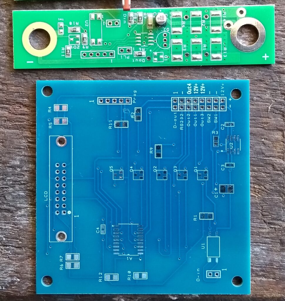
The BMS consists of two types of circuit boards. The smaller board is the CellTop Module board, and as the name suggests you fit one to each cell. It is powered by the cell, and so fits across the terminals.
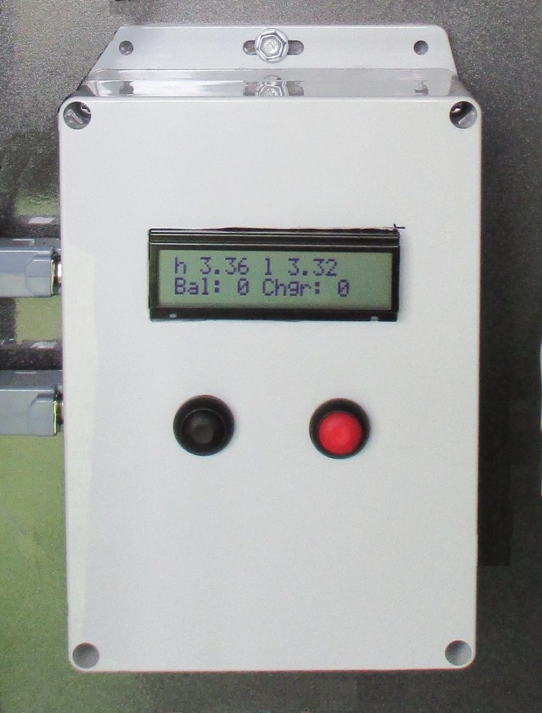
The larger board is the Master board. You can attach a screen and buttons, and the Master interprets what is going on with your battery.
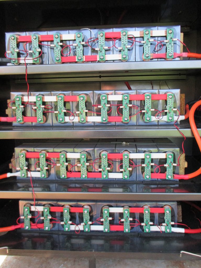
Each CellTop board connects to the next CellTop board via a two wire communications cable (red and black wires in the photos). The Master connects to the first and last CellTop board in a similar way, making a big loop of communications.
The Master board is always the same, and you just need one.
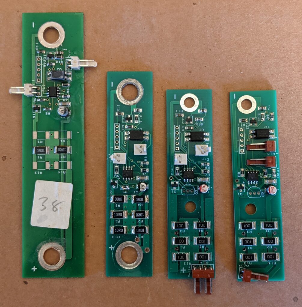
The CellTop Module boards connect to the terminals of the cell, and so the circuit board needs to be shaped to fit the cells you are using. See the photos for some different designs that I have made.
How do I make it?
To make this BMS you will need to:
- Download the circuit board files
- Adjust the CellTop design (if required for your cells)
- Get the circuit boards made
- Buy the electronic components
- Assemble the components on the boards
- Download the programming files
- Adjust the program(s) to suit your requirements
- Program the circuit boards
- Test the boards
Embarking on this project you will need to have or learn the following skills:
- Use DesignSpark software to modify circuit boards (if required for your cells)
- Use an online company to make circuit boards from your design
- Buy electronic components from online stores
- Assemble surface mount and through-hole electronic components to circuit boards
- Use MPLABX IDE software to make minor adjustments to C programs
- Use MPLABX IDE software to program cicruit boards
- Fault-find problems on circuit boards
Equipment you’ll need (as well as buying the components):
- A computer running Windows or Linux
- An oven or hotplate to assemble the surface-mount components on the PCBs
- A soldering iron to assemble the through-hole components on the PCBs
- A PICKIT programming tool
How cheap is it?
I’ve made this BMS for about $5 per Module, and perhaps $50 for the Master including box, buttons and LCD screen. So for a 45 cell electric vehicle battery it would be about $275, or for a 16 cell home battery it would be $130. Not bad for any BMS, let alone one with these features.
Let’s begin!
Follow through my articles and I’ll show you how to make this cheap but flexible open-source BMS:
The Low Cost BMS (this article)
How to Create Circuit Boards for the Low Cost BMS
How to Assemble the Circuit Boards for the Low Cost BMS
How to Program the Circuit Boards for the Low Cost BMS
hey, there is a way to have it fully assembled by jlcpcb, pcbway etc?
so bom+position for every part.
that should save a lot of work
Yes!
I investigated this when making the Module boards, since there are lots of those. The company I used to make my boards, Seeed, offered a service to populate the boards. They didn’t have all of the components, but I went ahead and had them made with the components that they could supply. This meant that I still had to assemble some components myself. This made it harder to do, and I wouldn’t do it that way again. I describe this in the article on assembling the boards.
If you can find a company that will do all of the components, that would be easier, although not cheap.
All of the information is in the Design Spark projects, Seeed was able to interpret that information to make and assemble the boards for me. You should be able to do the same if you can find a company that can assemble all the components.
Hi – Very neat design.
How does it determine the individual conditions in a parallel connected set? Isn’t the busbar going to be such a low impedance as to make any cell-top sensing impossible between the parallel connected cells?
I have two cells in parallel, with one board on each cell.
Each board has a temperature sensor, so the temperature of each cell is measured individually.
With the voltage, since the cells are tied together they will always be the same. So one board would do the same job for voltage.