How to make circuit boards for the Low Cost BMS
The Low Cost BMS is an open-source design for a Battery Management System, see my previous article for a description. Open source means that you can either make it exactly as-is, or modify the design yourself. This article walks you through how to make the circuit boards (PCBs) using the provided design.
Download the circuit board files
The circuit board files are at the Sourceforge site here: https://sourceforge.net/projects/low-cost-bms/files/Circuit_Boards/
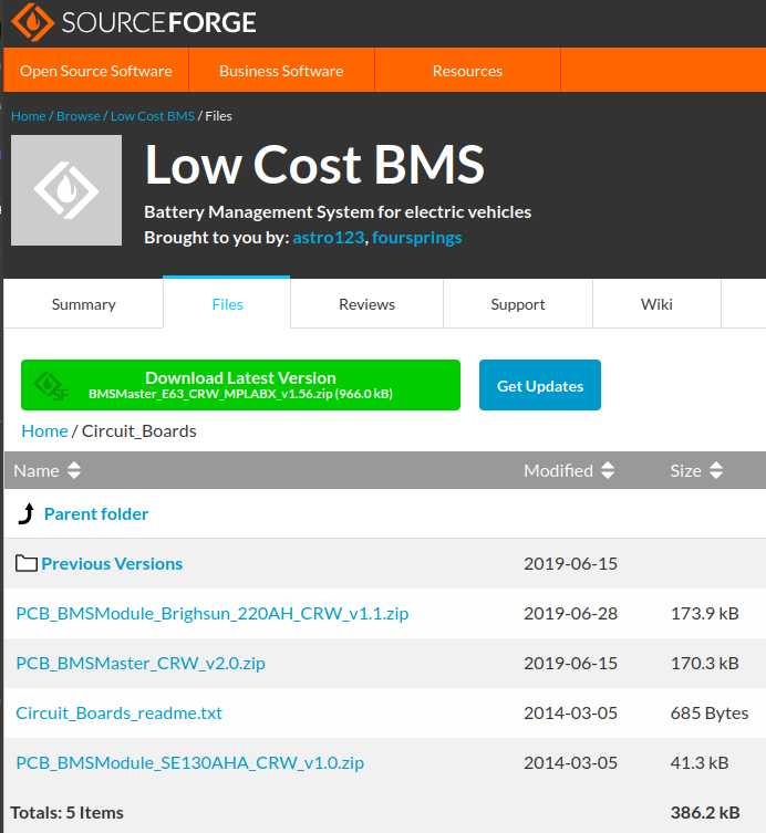
In this example screenshot you can see three zip files. One is for the Master board, you’ll need to download that one. The other two are for two different designs of Module boards. In the screenshot, one is for a Brighsun 220AH cell and one is for an SE130AHA cell. If you have one of these cells then download the corresponding file. If the cell you are using is not listed then you might like to download both of them and see which one suits you best.
In each zip file is a text file that describes all the included files. You can either use the .sch and .pcb files to modify the design, or just use the Gerber files to create the circuit board without modification.
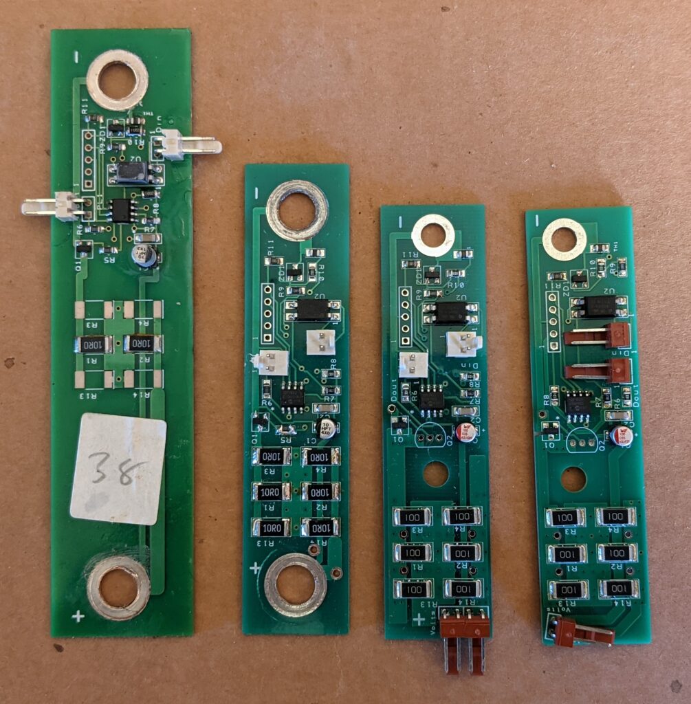
You need a Module board that will fit your cells. These boards are normally bolted between the terminals of the cells, and since the terminals are different sizes and spacings for each type of cell, there are several different versions available. Download each available version and check the readme file to see what the terminal spacing is. If none match your cells then you’ll need to modify one of the designs. If you do this, consider uploading your new design to Sourceforge so that others can use it!
Adjust the design of the circuit board(s)
The circuit boards are designed using DesignSpark PCB. This software is intimately tied to the large components company RS Components. They provide a free version, which has libraries of components sold by RS Components, in the hope that you’ll buy your components from them. You’ll need a free account to download and install this software: https://www.rs-online.com/designspark/pcb-download-and-installation
DesignSpark PCB is a Windows program, but I managed to get version 10.0 to work under Ubuntu using Wine. I followed this tutorial, including the amendments in the comments section at the bottom.
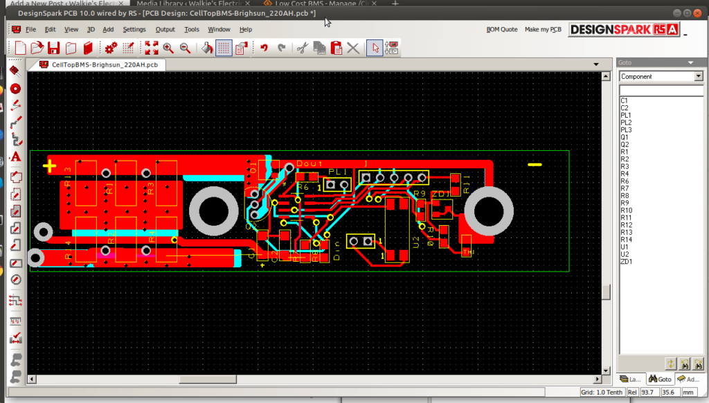
If you just want to adjust the terminal size and/or spacing, open the .pcb file in DesignSpark. Editing is reasonably intuitive for simple things, but doing much will require you to learn how the software works. Google will find you plenty of tutorials. A good function is Measure, under the Tools menu. This will help you get your terminal spacings correct.
Make the circuit boards
Once you are happy with your design you’ll want to get some boards made. Back in my day, you made circuit boards yourself, and it was a fiddly, messy, time-consuming job. These days the easiest and cheapest method is to upload your design to a company with an online ordering system, who will turn your design into PCBs, delivered to your door in a matter of days. The files to upload are called Gerber files, and they are not exactly simple to get from the DesignSpark software. I used Seeed Studio to create my circuit boards, and they provide this handy walkthrough to produce the Gerber files.
There are lots of PCB manufacturers out there, but Seeed Studios is a good one and I’ll use them for this example. First, go to their website order page: https://www.seeedstudio.com/fusion_pcb.html
- At the top you can add your Gerber files. These are either downloaded from the Sourceforge link described above, or if you have customised the board design yourself you’ll want to upload your own.
- The boards are two layers (unless you’ve changed that for your design).
- The dimensions of the board can be found using the Measure tool in DesignSpark.
- For everything else you can use the defaults.
There is a tickbox for PCB Assembly. Explore this if you would like the PCB company to source components for you and solder them to the board. I did this once, but Seeed did not have all of the components, so some places were left empty. This made it more difficult to place my own components later, as the pads had a convex layer of solder on them, and my components fell off. It also took quite a bit of effort to set up in the first place, it probably took me longer to set this up than it would have to solder all the components to 50 boards myself. I’d recommend that you don’t bother doing this unless you have a lot of boards to make, and then only do it if you can purchase every surface mount component through the service. Soldering the surface mount components yourself is reasonably straightforward, and I’ll describe it in detail in a later article.
Another tickbox is SMT Stencil. This is a stencil that they can provide to help you apply solder paste to the boards. You don’t strictly require one of these, but I found that they are very handy, making the board assembly process quicker. So if you can afford it, buy one of these for your boards, especially if you are going to make lots of them. You might choose to order one for your CellTop Module boards, but not for your Master. You don’t want a frame for your stencil.
The price per board drops dramatically once your order quantity climbs higher. If you are certain of your design then it’s a good idea to order more than you need, as things can go wrong with assembly, and it is often easier to assemble a new board than fault-find an existing one. But if you have made major changes to the design then you might want to purchase just a couple to test them out first.
I was surprised at how fast these boards were made for me. On one occasion I ordered components from Australia and boards from China on the same day, and the boards arrived first!
The complete set of articles include:
The Low Cost BMS
How to Create Circuit Boards for the Low Cost BMS (this article)
How to Assemble the Circuit Boards for the Low Cost BMS
How to Program the Circuit Boards for the Low Cost BMS
Hi. I live in NSW offgrid on small acreage. I am looking to change over from second hand ups cells to lithium (maybe eve 304ah). I hope to have at least 3 banks of 16 cells. I too have a selectronic inverter but am finding it impossible to get information on a bms. At first I was looking at unmanaged jk bms but after looking online people (qualified I don’t know) suggest if you have multiple batteries in parallel then there should be some communication with the inverter to identify there are three banks so inverter/charger changes charge current if one bank goes off line. Any guidance would be appreciated. Everyone on YouTube university seem to have Victron gear and no one seems to dabble in selectronic (probably the price). I contacted Batrium and they told me they can’t guarantee as people have tried to contact selectronic and they are not forthcoming with information.
Thanks, I am slowly reading your brumby blog finding it fascinating.
Grant
Hi Grant,
Fill in the contact form and I’ll send you an email reply.