How to purchase components and solder them to your circuit boards
The Low Cost BMS is an open-source design for a Battery Management System, see my previous article for a description. This article walks you through how to assemble your boards. Don’t be put off if you haven’t assembled surface-mount components before, it is easier than you might think!
Customise your components list
If you’re happy with the design as-is, then you can skip to the section on buying the components. But open-source is all about modifying things to suit your needs, so let’s first discuss some different components that you might like to substitute.
Bypass Resistors
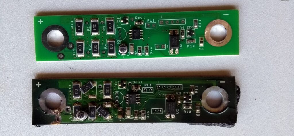
The resistors R1, 2, 3, 4, 13 & 14 on the CellTop Module board control the maximum bypass current for balancing. The current can be controlled via software from zero up to this maximum. In the design I’ve specified 10 Ohm resistors, which gives a maximum bypass current of about 600 mA. I’ve used the 10 Ohm resistors each time I’ve made this BMS, and I think that this should be fine in most situations, see my previous article for the reasons why. If you want to though, you can increase or decrease the maximum current by choosing different bypass resistors, and in this section I’ll go through the maths to show you how.
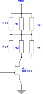
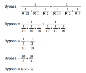
The six bypass resistors are in an array of three in parallel, two in series. They are distributed over the board in a pattern to help dissipate heat. I’ve used six resistors of 10 Ohms each. This adds up to 6.667 Ohms, as per the picture above.
The formula to calculate the bypass current is I=V/R. For a 4 V cell this would be a maximum current of 0.6 A. The power dissipated is V*I = 2.4 W total. This is divided between the six resistors and gives 0.4 W per resistor. I’ve used 1 W resistors, so you can see that they are running within tolerance. Theoretically I can run these bypass resistors in hot conditions with no problems.
To increase the bypass current you have several options:
You could use a surface mount resistor with a lower resistance. For instance a 5 Ohm resistor would give half the resistance and double the current. This would be only just within the specifications of a 1 W resistor though, so I’d not want to do this in a situation that might have high ambient temperatures.
On some boards there are holes for two parallel axial (through-hole) resistors. Because these are off the board, axial resistors can dissipate more energy before they get too hot. For instance if you wanted to bypass 1 A, you’d need 4 Ohms of resistance. This can be done with two 8 Ohm resistors in parallel, and they’d need to be able to dissipate 4 W in total, or 2 W per resistor. A quick look at the website of an online components company finds an 8 Ohm, 5 W resistor for $2.50.
Bypass Transistor
The surface-mount MOSFET specified in the design will theoretically switch up to 5.4 A, although it would probably need better heatsinking if you wanted to use it for currents that high. You could replace this MOSFET with a through-hole device if you were making a higher current design. Some of the board designs already have a place for a through-hole device, or you can modify it yourself.
Buy the Electronic Components
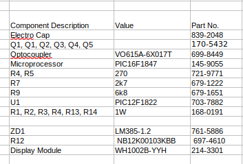
Once you’re happy with any design changes, you’re ready to purchase your components. In the Master circuit board files that you downloaded (see this article) there should be a Bill of Materials (BoM) file. This spreadsheet lists all of the components for both Master and CellTop Module boards. It is a bit of a mess (sorry), but the first tab is the most important. The top part is for the Master and the bottom part is for the Module. All of the components are listed, the number you need per board and part numbers from different suppliers. RS Components and Element 14 are likely to have all of the components, but places like Rockby can be significantly cheaper, and that can add up if you have lots of boards to make.
Assemble the boards
Surface-mount components should be assembled first, put them all on before the through-hole components. You’ll need:
- Solder paste (sold in a syringe, this has an expiry date and should be kept in the fridge)
- Solder stencil (if you bought one when you bought your boards)
- If using a solder stencil, a putty knife to spread the solder paste
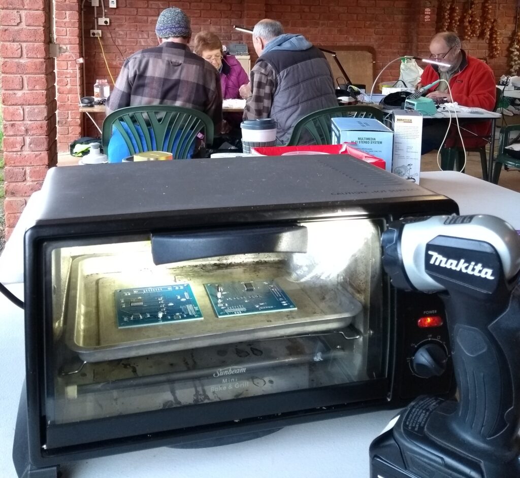
- Oven for baking the boards. I purchased the Sunbeam Mini Bake and Grill. This was very cheap and you can use it for food as well!
- Tweezers for placing components. I like the tweezers that spring closed (squeeze to open)
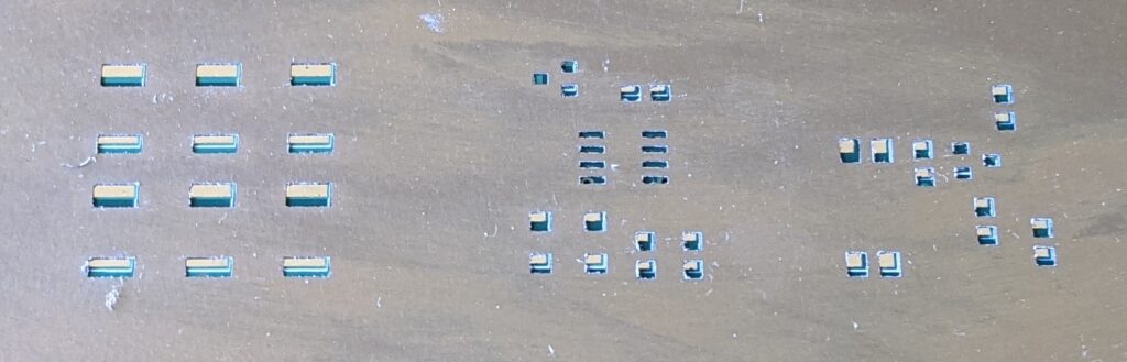
First place the solder paste on your boards. If using a syringe, dab an amount of paste onto each of the surface-mount pads (don’t do the through-hole component pads). You don’t need to be too neat, when heated the solder beads on top of the pads. I found that this video is useful to see it being done.
A solder stencil will make things quicker if you have more than a couple of boards to do. It takes a little while to set up, but is then very quick per board to apply the solder. Watch this video for the technique, and I’ll try to explain it here.
Note that your stencil has holes to let the solder through onto the solder pads, but it needs to match up precisely. Allocate a section of table or a wooden board for the process. Using tape, make an L shape with old circuit boards, or with something else the same height as your PCBs. Then you can slide your PCB into place into the L, and it will be in a precise position. Position your stencil over the top and line it up with the PCB. Tape the stencil in place on one end. Practice putting a new PCB into place and seeing that it lines up correctly.
Solder mask over PCB, not aligned. 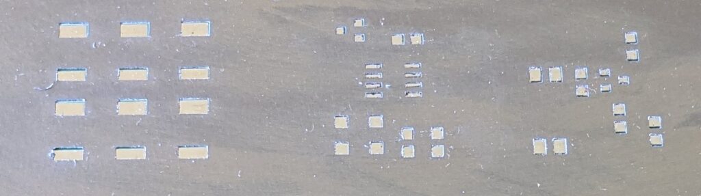
Solder mask aligned over PCB.
Once in place, you’re ready to spread on some paste. Use the putty knife to spread solder over the stencil like you are spreading butter over bread. Then go back over the board again, this time angling the knife so that it picks up the solder that you just laid down. Then carefully remove your PCB and inspect. It should have neat squares of paste over the solder pads.
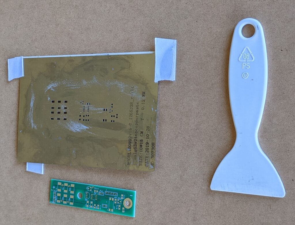
In this photo the solder mask is held in place along the top side with double-sided tape. The PCB is inserted under the mask. This spatula is a plastic scraper from a freezer.
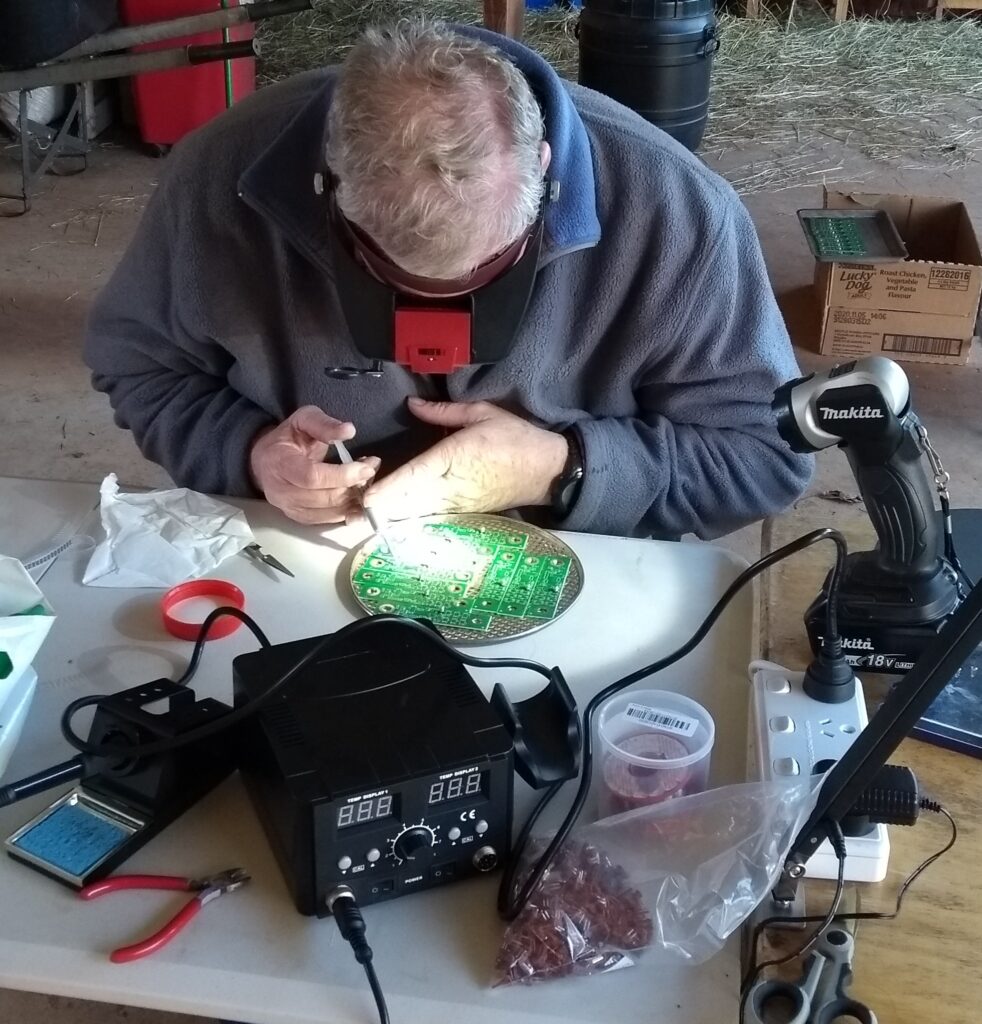
Once the solder is in place you can place your components. Identify which component you are placing, and where it goes. Pick it up with the tweezers and carefully place it onto the solder pads. It should stick to the solder so it won’t bump off easily. Make sure that paste is adhering to the metal surfaces of both the component and the pad. Again, it doesn’t need to be neat, the components have a habit of moving into place with surface tension when the solder melts in the oven. You can place resistors or small capacitors upside down if you like, it doesn’t matter. But make sure that the multi-legged components and the large electrolytic capacitors are the right way around.
If doing a lot of boards I’ll tend to set up a tray full, and place the same component on each board. So I’ll place R1 on 10 boards, then R2 on those same 10 boards. Make sure that you place all the surface mount components before putting the board in the oven.
Set the oven to about 200°C and leave it for a few minutes to pre-heat. The oven I use goes way over temperature at first, so pre-heating is essential to avoid overheating the boards.
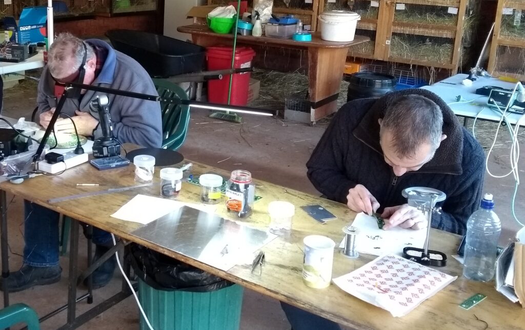
Once the oven is settled, carefully insert the tray with the boards in it and shut the door, noting the time. Watch the blobs of solder paste, after a few minutes they will melt. You can see them change colour from grey to silver, and they move a bit as surface tension takes over. It can take from 2-5 minutes to start melting. Watch them (a torch is handy) until they are all melted, then give it 30 seconds more.
If you’re only doing one batch then turn the oven off, open the door and let it all cool down. If you have another batch to do then you can carefully remove the tray and let it cool on a bench. Be very careful though, as the solder is still liquid at this stage so any sudden move will ruin all your hard work!
Once cooled down enough you can check your handiwork. A soldering iron with a fine tip is useful to fix any mistakes. Then you can solder in the through-hole components.
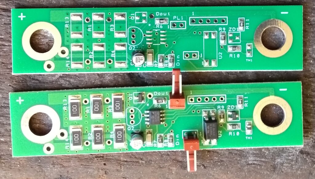
Finished!
The next job is to program the boards, which I describe in my article: Programming the Circuit Boards
The complete series of articles include:
The Low Cost BMS
How to Create Circuit Boards for the Low Cost BMS
How to Assemble the Circuit Boards for the Low Cost BMS (this article)
How to Program the Circuit Boards for the Low Cost BMS